Intro to Computer Engineering
Studio 7 - From a Motor to a Car

Introduction
Click here to access the Canvas page with the repository for this studio.
Objectives
The topic of today’s studio is to experiment with controlling something in the physical world. We will start with controlling a motor, and then use a pair of motors to control a semi-autonomous car.
By the end of this studio you should know:
- how to control an analog output.
- how to drive a DC motor.
The Studio
We will start by following the instructions provided by SparkFun in their Motor Basics tutorial. If you position the motor driver as indicated in the tutorial, that will leave space for the ultrasonic sensor (which will be used in the assignment). The sketch is available in your repo for this studio under the name MotorBasics. It is literally the same as the sketch on the SparkFun website, so if you use different pins to wire up your motor, be sure to alter the sketch appropriately.
Notice how different speeds are delivered to the motor via the analogWrite() method. Let’s explore how that works in a little more detail. In Chapter 4 of the text, a pulse width modulated (PWM) output is really just a digital output that cycles between low voltage (e.g., 0V) and high voltage (e.g., 5V) frequently enough that we perceive the average value rather than the instantaneous value. The fraction of the time that the output is high will determine the average value.
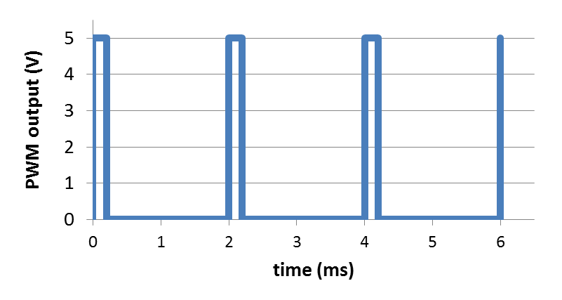
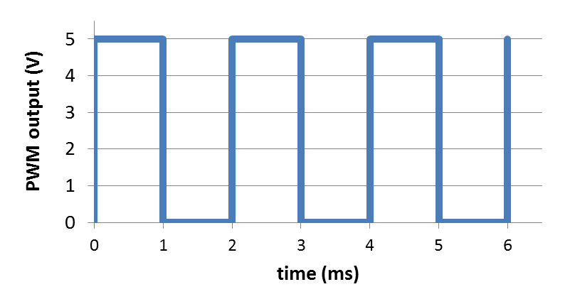
The three figures below illustrate a PWM analog output at 10% of full scale, 50% of full scale, and 90% of full scale.
At 10% of full scale, the waveform looks like this:
At 50% of full scale, the waveform looks like this:
At 90% of full scale, the waveform looks like this:
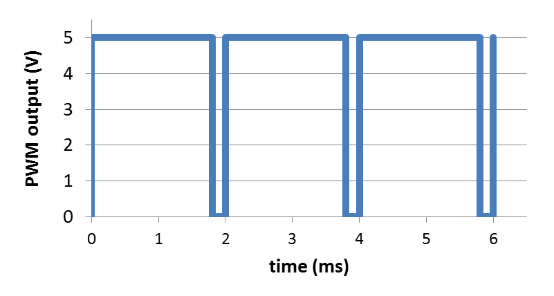
Also note that the period of the signal is 2 ms, corresponding to 500 Hz. What this means, from a practical point of view, is that the output signal must be filtered (smoothed) enough that the 500 Hz pulses are evened out and the waveform average is what the attached device responds to. This is easily the case for our motors.
The current requirements of our motor are such that we cannot drive the motor directly from the PWM output pins on the Arduino. Instead, we need to use the motor driver chip. However, the concept is exactly the same. The motor driver chip is simply increasing the current capability to drive the motor.
Build a Car
Our next task is to use the motors (two of them) to drive the wheels of a car. OK, not a very big car, but a mobile device that can move on its own. Here is a picture of what it will look like:
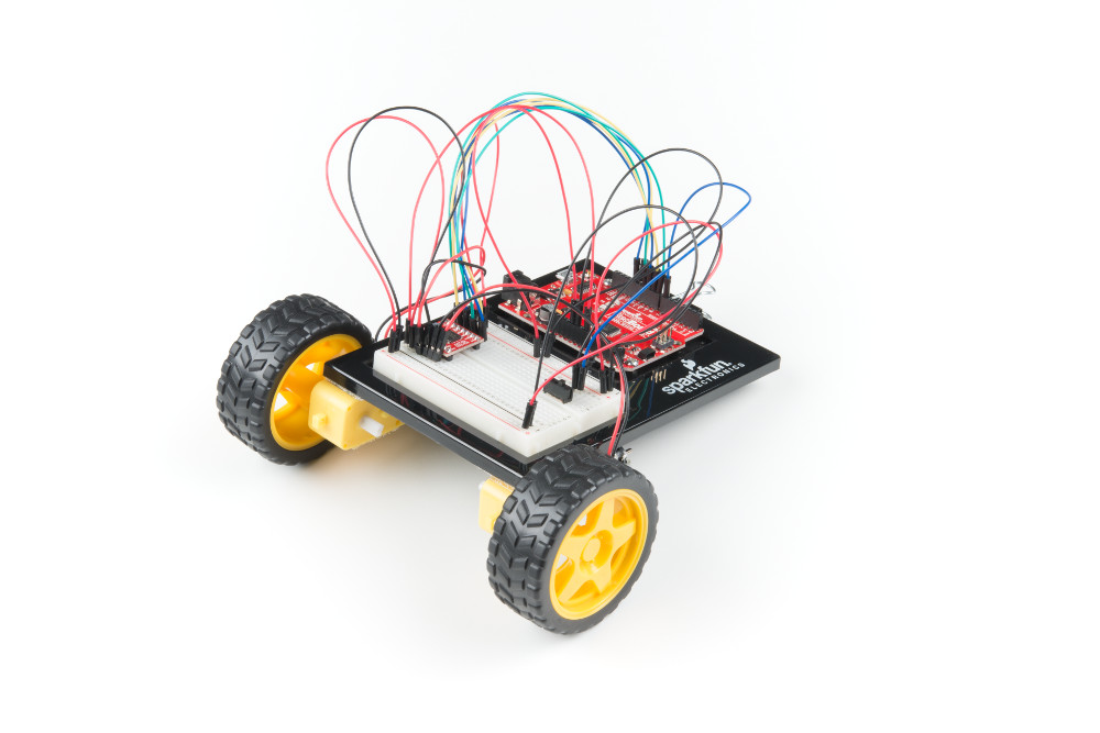
SparkFun’s Remote Controlled Robot tutorial shows how to do the physical construction.
The sketch (from SparkFun) is available in your repo for this studio under the name RemoteControlRobot.
If you aren’t using the same pins to wire everything up, make sure to alter the appropriate pin initializations in the sketch.
Experiment with the various controls that the provided sketch supports. How straight is it when driving forward? Does it go the same distance backward when commanded to do so? How accurate is its turning? You might adjust the motor speed (especially associated with the 'f' command) for the right and left motors so that when going forward it goes fairly straight.
Finish up
- Commit your code and verify in your web browser that it is all there.
- Get checked out by a TA.
Changes to repo structure:
MotorBasics/MotorBasics.ino
RemoteControlRobot/RemoteControlRobot.ino
Key Concepts
- Analog Output
- Pulse Width Modulation (PWM)
Generated at 2026-06-06 01:31:31 +0000.
Page written by Roger Chamberlain.